| Link Budget Calculations
After we already decided antenna heights for each link we should calculate link budget for each link to find antenna diameter, link RX & Availability as the following steps
2.5.1- Go to Worksheets from Modules menu or by pressing ctrl W. you get work sheet page as shown in Fig. 2.5.1
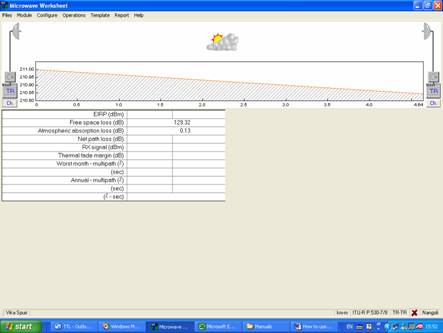
Fig. 2.5.1
2.5.2- Enter Point frequency & polarization at each site by pressing on Ch. Then click OK As shown in Fig. 2.5.1 & 2.5.2
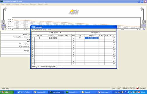
Fig. 2.5.2
2.5.3- Select Radio Equipment type by clicking on TR you will get Radio Equipment page as shown in Fig. 2.5.3
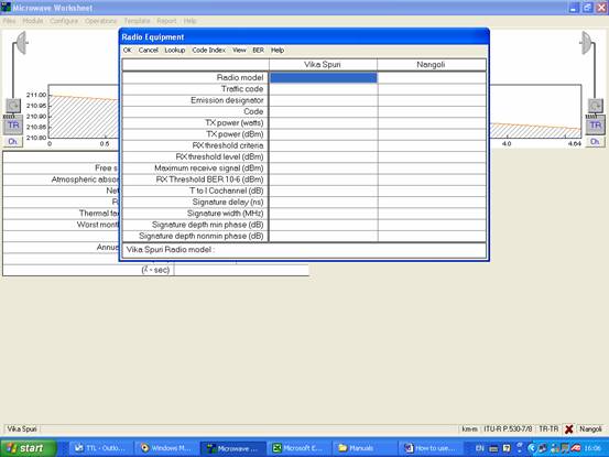
Fig. 2.5.3
2.5.4- click on Code Index then New Index. Go to your pathloss folder – Equipment – MRS – NEC (where you placed NEC equipment folder) as shown in Fig. 2.5.4
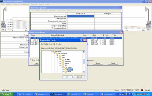
Fig. 2.5.4
2.5.5- Select your radio according to Type (3000S , Pasolink , Pasolink+ , …..) , Frequency ban (7G , 8G , 11G, …….) Modulation (16 QAM , 32 QAM , 128 QAM,….) Capacity (PDH x E1 , STM-0 , STM-1) then click Both to set same Radio for both stations then Press OK as shown in Fig. 2.5.5
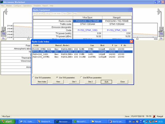
Fig. 2.5.5
2.5.6- Set Branching Circuit or Hybrid Loss by clicking on its Symbol (above TR) then press OK as shown in Fig. 2.5.6
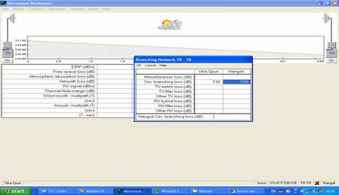
Fig. 2.5.6
2.5.7- Enter Feeder Data & connection losses by pressing on Wave Guide symbol then kick OK as shown in Fig. 2.5.7
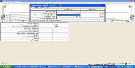
Fig. 2.5.7
2.5.8- Select antenna type for each station by clicking on antenna symbol then press as shown in Fig. 2.5.8
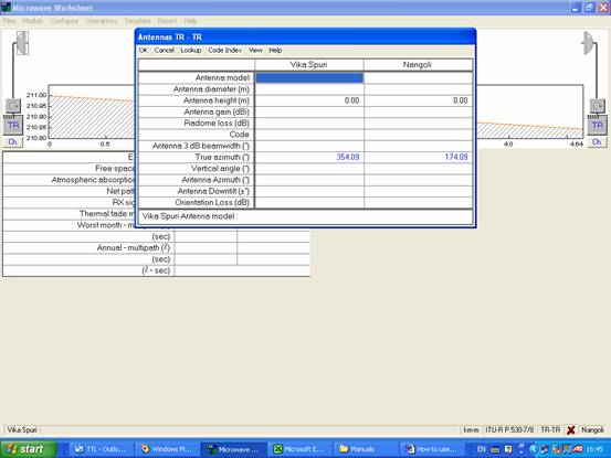
Fig. 2.5.8
2.5.9- Press on Code Index then New Index then brows for pathloss folder (where you placed it) – Equipment – MAS – Antenna manufacturer (Andrew, RFS, …..) – Frequency Range (102-132 , 122 – 132 , 142 – 153 , …….)then press OK as shown in Fig. 2.5.9
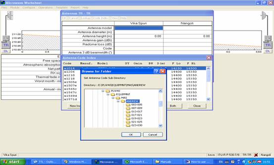
Fig. 2.5.9
2.5.10- Select antenna for site 1 & press on Site 1 & select antenna for site 2 & press Site 2 or in case of both sites have same antenna press on Both. The press Close – OK as shown in Fig. 2.5.10
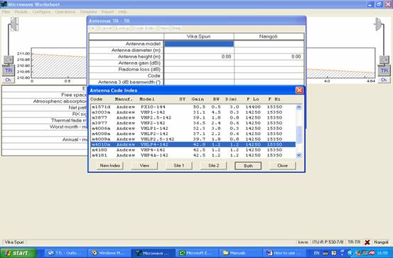
Fig. 2.5.10
2.5.11- Set Reliability Method
In worksheet page go to Operation Menu – reliability Methods as per attached in Fig. 2.5.11
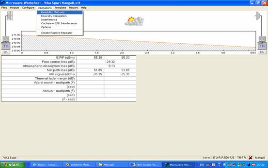
Fig. 2.5.11
Set Reliability criteria as per shown in Fig. 2.5.11-1 for SDH or as Project & Customer requirement & press OK
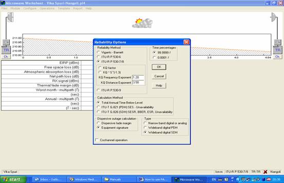
Fig. 2.5.11.1
2.5.12- Set of Rain factor
Press on Rain symbol – select ITU-R-P-530. 6/8 – press Load Rain File – Select Rain area according to ITU-530 Map Fig. 1.2.3 (Rain Files are placed in Pathloss folder – Rain) – Press Close as per shown in Fig. 2.5.12
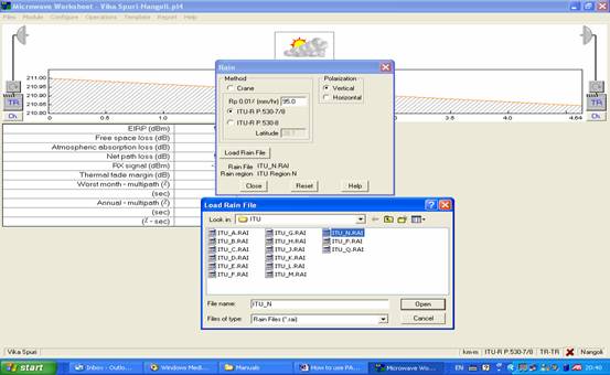
Fig. 2.5.12
2.5.13- Set Geoclimatic Factor
Press on the Ground Symbol (as shown in Fig. 2.5.13-1) – Set Geoclimatic Factor according to ITU-R-P-453 as Shown in Fig. 2.5.13-2)
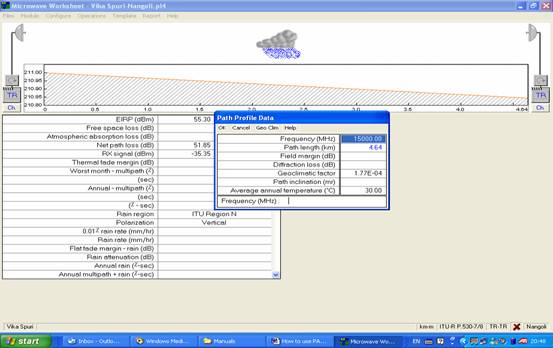
Fig. 2.5.13-1
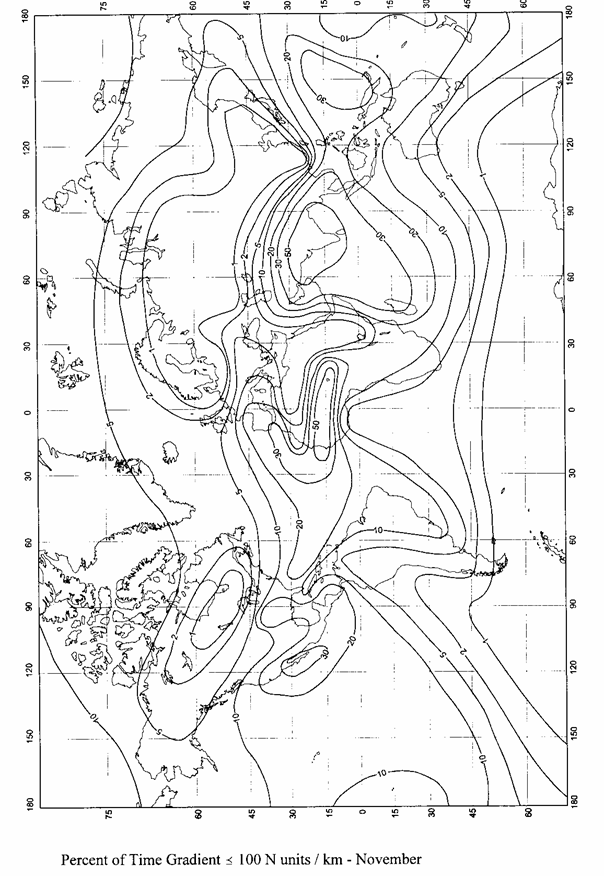
Fig. 2.5.13-2
2.5.14- Make sure of either our Path Calculation is correct or we need to revise again. To do that please check the followings
- Make sure that your worksheet page has Green Correct sign in Right Bottom of screen. If it is wrong sign that's mean there are some data mistake
- Have a look to RX Signal, Fade Margin & (Annual Availability with rain) Percentage as per shown in Fig. 2.5.14
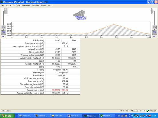
Fig. 2.5.14
- If any of (RX, Margin, Availability) is less than the required to meet the Spec. & recommendations. You have to increase antenna diameter or add Space Diversity Radio to reach to the required Spec.
- So you go to step 2.5.10 again & select new antennas
2.5.15- After finish of path calculations go to Report Menu in Worksheet page – click Full Report
You will get full path calculation report as below one. You can copy it to Word or Excel sheet & save it for reference & submitting with your survey report
Microwave Worksheet - Vika Spuri-Nangoli.pl4
Vika Spuri Nangoli
Elevation (m) 211.00 210.84
Latitude 28 38 24.30 N 28 40 54.20 N
Longitude 077 04 28.80 E 077 04 11.20 E
True azimuth (°) 354.09 174.09
Vertical angle (°) -0.02 -0.01
Antenna model VHP6-142 VHP6-142
Antenna height (m) 0.00 0.00
Antenna gain (dBi) 46.00 46.00
TX line length (m) 0.60 0.60
TX line unit loss (dB /100 m) 100.00 100.00
TX line loss (dB) 0.60 0.60
Circ. branching loss (dB) 3.50 3.50
Frequency (MHz) 15000.00
Polarization Vertical
Path length (km) 4.64
Free space loss (dB) 129.32
Atmospheric absorption loss (dB) 0.13
Net path loss (dB) 45.65 45.65
Radio model PASOLINK+ 15G 155MB PASOLINK+ 15G 155MB
TX power (watts) 0.04 0.04
TX power (dBm) 16.50 16.50
EIRP (dBm) 58.40 58.40
TX Channels 1 14543.0000V 1' 14963.0000V
RX threshold criteria BER 10-6 BER 10-6
RX threshold level (dBm) -67.50 -67.50
RX signal (dBm) -29.15 -29.15
Thermal fade margin (dB) 38.35 38.35
Geoclimatic factor 1.77E-04
Path inclination (mr) 0.03
Average annual temperature (°C) 30.00
Worst month - multipath (%) 99.99993 99.99993
(sec) 1.88 1.88
Annual - multipath (%) 99.99997 99.99997
(sec) 8.48 8.48
(% - sec) 99.99995 - 16.95
Rain region ITU Region N
0.01% rain rate (mm/hr) 95.00
Flat fade margin - rain (dB) 38.35
Rain rate (mm/hr) 186.44
Rain attenuation (dB) 38.35
Annual rain (%-sec) 99.99916 - 264.20
Annual multipath + rain (%-sec) 99.99911 - 281.15
ÇáÇÍI, NEíÚ ÇáÇaá 10 1424
Reliability Method - ITU-R P.530-7/8
Rain - ITU-R P530-7
|