|
Cisco Exploration Semester 1 Chapter 7
7. Data Link Layer
To support our communication, the OSI model divides the functions of a data network into layers.
To recap:
The Application layer provides the interface to the user.
The Transport layer is responsible for dividing and managing communications between the processes running in the two end systems.
The Network layer protocols organize our communication data so that it can travel across internetworks from the originating host to a destination host.
For Network layer packets to be transported from source host to destination host, they must traverse different physical networks. These physical networks can consist of different types of physical media such as copper wires, microwaves, optical fibers, and satellite links. Network layer packets do not have a way to directly access these different media.
It is the role of the OSI Data Link layer to prepare Network layer packets for transmission and to control access to the physical media.
This chapter introduces the general functions of the Data Link layer and the protocols associated with it.
Learning Objectives
Upon completion of this chapter, you will be able to:
- Explain the role of Data Link layer protocols in data transmission.
- Describe how the Data Link layer prepares data for transmission on network media.
- Describe the different types of media access control methods.
- Identify several common logical network topologies and describe how the logical topology determines the media access control method for that network.
- Explain the purpose of encapsulating packets into frames to facilitate media access.
- Describe the Layer 2 frame structure and identify generic fields.
- Explain the role of key frame header and trailer fields, including addressing, QoS, type of protocol, and Frame Check Sequence.
7.1.1 Supporting & Connecting to Upper Layer Services
The Data Link layer provides a means for exchanging data over a common local media.
The Data Link layer performs two basic services:
Allows the upper layers to access the media using techniques such as framing
Controls how data is placed onto the media and is received from the media using techniques such as media access control and error detection
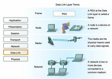
As with each of the OSI layers, there are terms specific to this layer:
Frame - The Data Link layer PDU
Node - The Layer 2 notation for network devices connected to a common medium
Media/medium (physical)* - The physical means for the transfer of information between two nodes
Network (physical)** - Two or more nodes connected to a common medium
The Data Link layer is responsible for the exchange of frames between nodes over the media of a physical network.
* It is important to understand the meaning of the words medium and media within the context of this chapter. Here, these words refer to the material that actually carries the signals representing the transmitted data. Media is the physical copper cable, optical fiber, or atmosphere through which the signals travel. In this chapter media does not refer to content programming such as audio, animation, television, and video as used when referring to digital content and multimedia.
** A physical network is different from a logical network. Logical networks are defined at the Network layer by the arrangement of the hierarchical addressing scheme. Physical networks represent the interconnection of devices on a common media. Sometimes, a physical network is also referred to as a network segment.
Upper Layer Access to Media
As we have discussed, a network model allows each layer to function with minimal concern for the roles of the other layers. The Data Link layer relieves the upper layers from the responsibility of putting data on the network and receiving data from the network. This layer provides services to support the communication processes for each medium over which data is to be transmitted.
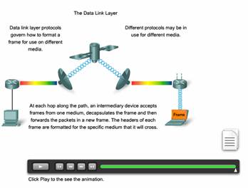
In any given exchange of Network layer packets, there may be numerous Data Link layer and media transitions. At each hop along the path, an intermediary device - usually a router - accepts frames from a medium, decapsulates the frame, and then forwards the packet in a new frame appropriate to the medium of that segment of the physical network.
Imagine a data conversation between two distant hosts, such as a PC in Paris with an Internet server in Japan. Although the two hosts may be communicating with their peer Network layer protocols (IP for example), it is likely that numerous Data Link layer protocols are being used to transport the IP packets over various types of LANs and WANs. This packet exchange between two hosts requires a diversity of protocols that must exist at the Data Link layer. Each transition at a router could require a different Data Link layer protocol for transport on a new medium.
Notice in the figure that each link between devices uses a different medium. Between the PC and the router may be an Ethernet link. The routers are connected through a satellite link, and the laptop is connected through a wireless link to the last router. In this example, as an IP packet travels from the PC to the laptop, it will be encapsulated into Ethernet frame, decapsulated, processed, and then encapsulated into a new data link frame to cross the satellite link. For the final link, the packet will use a wireless data link frame from the router to the laptop.
The Data Link layer effectively insulates the communication processes at the higher layers from the media transitions that may occur end-to-end. A packet is received from and directed to an upper layer protocol, in this case IPv4 or IPv6, that does not need to be aware of which media the communication will use.
Without the Data Link layer, a Network layer protocol, such as IP, would have to make provisions for connecting to every type of
71.2 Controlling Transfer Across Local Media
Layer 2 protocols specify the encapsulation of a packet into a frame and the techniques for getting the encapsulated packet on and off each medium. The technique used for getting the frame on and off media is called the media access control method. For the data to be transferred across a number of different media, different media access control methods may be required during the course of a single communication.
Each network environment that packets encounter as they travel from a local host to a remote host can have different characteristics. For example, one network environment may consist of many hosts contending to access the network medium on an ad hoc basis. Another environment may consist of a direct connection between only two devices over which data flows sequentially as bits in an orderly way.
The media access control methods described by the Data Link layer protocols define the processes by which network devices can access the network media and transmit frames in diverse network environments.
A node that is an end device uses an adapter to make the connection to the network. For example, to connect to a LAN, the device would use the appropriate Network Interface Card (NIC) to connect to the LAN media. The adapter manages the framing and media access control.
At intermediary devices such as a router, where the media type could change for each connected network, different physical interfaces on the router are used to encapsulate the packet into the appropriate frame, and a suitable media access control method is used to access each link. The router in the figure has an Ethernet interface to connect to the LAN and a serial interface to connect to the WAN. As the router processes frames, it will use Data Link layer services to receive the frame from one medium, decapsulate it to the Layer 3 PDU, re-encapsulate the PDU into a new frame, and place the frame on the medium of the next link of the network.
7.1.3 Creating a Frame
The description of a frame is a key element of each Data Link layer protocol. Data Link layer protocols require control information to enable the protocols to function. Control information may tell:
- Which nodes are in communication with each other
- When communication between individual nodes begins and when it ends
- Which errors occurred while the nodes communicated
- Which nodes will communicate next
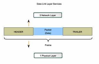
The Data Link layer prepares a packet for transport across the local media by encapsulating it with a header and a trailer to create a frame.
Unlike the other PDUs that have been discussed in this course, the Data Link layer frame includes:
- Data - The packet from the Network layer
- Header - Contains control information, such as addressing, and is located at the beginning of the PDU
- Trailer - Contains control information added to the end of the PDU
- These frame elements will be discussed in more detail later in this chapter.
Formatting Data for Transmission
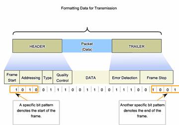
When data travels on the media, it is converted into a stream of bits, or 1s and 0s. If a node is receiving long streams of bits, how does it determine where a frame starts and stops or which bits represent the address?
Framing breaks the stream into decipherable groupings, with control information inserted in the header and trailer as values in different fields. This format gives the physical signals a structure that can be received by nodes and decoded into packets at the destination.
Typical field types include:
- Start and stop indicator fields - The beginning and end limits of the frame
- Naming or addressing fields
- Type field - The type of PDU contained in the frame
- Quality - control fields
- A data field -The frame payload (Network layer packet)
Fields at the end of the frame form the trailer. These fields are used for error detection and mark the end of the frame.
Not all protocols include all of these fields. The standards for a specific Data Link protocol define the actual frame format. Examples of frame formats will be discussed at the end of this chapter.
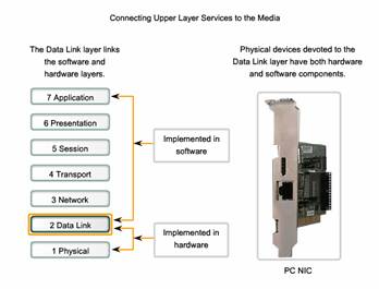
7.1.4 Connecting Upper Layer Services to The Media
The Data Link layer exists as a connecting layer between the software processes of the layers above it and the Physical layer below it. As such, it prepares the Network layer packets for transmission across some form of media, be it copper, fiber, or the atmosphere.
In many cases, the Data Link layer is embodied as a physical entity, such as an Ethernet network interface card (NIC), which inserts into the system bus of a computer and makes the connection between running software processes on the computer and physical media. The NIC is not solely a physical entity, however. Software associated with the NIC enables the NIC to perform its intermediary functions of preparing data for transmission and encoding the data as signals to be sent on the associated media.
7.1.4 Connecting Upper Layer Services to The Media
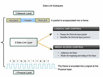
Data Link Sublayers
To support a wide variety of network functions, the Data Link layer is often divided into two sublayers: an upper sublayer and an lower sublayer.
The upper sublayer defines the software processes that provide services to the Network layer protocols.
The lower sublayer defines the media access processes performed by the hardware.
Separating the Data Link layer into sublayers allows for one type of frame defined by the upper layer to access different types of media defined by the lower layer. Such is the case in many LAN technologies, including Ethernet.
The two common LAN sublayers are:
Logical Link Control
Logical Link Control (LLC) places information in the frame that identifies which Network layer protocol is being used for the frame. This information allows multiple Layer 3 protocols, such as IP and IPX, to utilize the same network interface and media.
Media Access Control
Media Access Control (MAC) provides Data Link layer addressing and delimiting of data according to the physical signaling requirements of the medium and the type of Data Link layer protocol in use.
7.1.6 Standart
Unlike the protocols of the upper layers of the TCP/IP suite, Data Link layer protocols are generally not defined by Request for Comments (RFCs). Although the Internet Engineering Task Force (IETF) maintains the functional protocols and services for the TCP/IP protocol suite in the upper layers, the IETF does not define the functions and operation of that model's Network access layer. The TCP/IP Network Access layer is the equivalent of the OSI Data Link and Physical layers. These two layer will be discussed in separate chapters for closer examination..
The functional protocols and services at the Data Link layer are described by engineering organizations (such as IEEE, ANSI, and ITU) and communications companies. Engineering organizations set public and open standards and protocols. Communications companies may set and use proprietary protocols to take advantage of new advances in technology or market opportunities.
Data Link layer services and specifications are defined by multiple standards based on a variety of technologies and media to which the protocols are applied. Some of these standards integrate both Layer 2 and Layer 1 services.
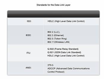
Engineering organizations that define open standards and protocols that apply to the Data Link layer include:
International Organization for Standardization (ISO)
Institute of Electrical and Electronics Engineers (IEEE)
American National Standards Institute (ANSI)
International Telecommunication Union (ITU)
Unlike the upper layer protocols, which are implemented mostly in software such as the host operating system or specific applications, Data Link layer processes occur both in software and hardware. The protocols at this layer are implemented within the electronics of the network adapters with which the device connects to the physical network.
For example, a device implementing the Data Link layer on a computer would be the network interface card (NIC). For a laptop, a wireless PCMCIA adapter is commonly used. Each of these adapters is the hardware that complies with the Layer 2 standards and protocols.
http://www.iso.org
http://www.ieee.org
http://www.ansi.org
http://www.itu.int
7.2.1 Placing Data on The Media
Regulating the placement of data frames onto the media is known as media access control. Among the different implementations of the Data Link layer protocols, there are different methods of controlling access to the media. These media access control techniques define if and how the nodes share the media.
Media access control is the equivalent of traffic rules that regulate the entrance of motor vehicles onto a roadway. The absence of any media access control would be the equivalent of vehicles ignoring all other traffic and entering the road without regard to the other vehicles.
However, not all roads and entrances are the same. Traffic can enter the road by merging, by waiting for its turn at a stop sign, or by obeying signal lights. A driver follows a different set of rules for each type of entrance.
In the same way, there are different ways to regulate the placing of frames onto the media. The protocols at the Data Link layer define the rules for access to different media. Some media access control methods use highly-controlled processes to ensure that frames are safely placed on the media. These methods are defined by sophisticated protocols, which require mechanisms that introduce overhead onto the network.
The method of media access control used depends on:
Media sharing - If and how the nodes share the media
Topology - How the connection between the nodes appears to the Data Link layer
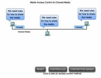
7.2.2 Media Access Control for Shared Media
Some network topologies share a common medium with multiple nodes. At any one time, there may be a number of devices attempting to send and receive data using the network media. There are rules that govern how these devices share the media.
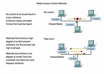
There are two basic media access control methods for shared media:
Controlled - Each node has its own time to use the medium
Contention-based - All nodes compete for the use of the medium
Click the tabs in the figure to see the differences in the two methods.
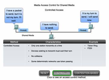
Controlled Access for Shared Media
When using the controlled access method, network devices take turns, in sequence, to access the medium. This method is also known as scheduled access or deterministic. If a device does not need to access the medium, the opportunity to use the medium passes to the next device in line. When one device places a frame on the media, no other device can do so until the frame has arrived at the destination and has been processed by the destination.
Although controlled access is well-ordered and provides predictable throughput, deterministic methods can be inefficient because a device has to wait for its turn before it can use the medium.
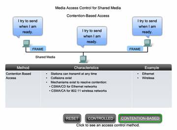
Contention-based Access for Shared Media
Also referred to as non-deterministic, contention-based methods allow any device to try to access the medium whenever it has data to send. To prevent complete chaos on the media, these methods use a Carrier Sense Multiple Access (CSMA) process to first detect if the media is carrying a signal. If a carrier signal on the media from another node is detected, it means that another device is transmitting. When the device attempting to transmit sees that the media is busy, it will wait and try again after a short time period. If no carrier signal is detected, the device transmits its data. Ethernet and wireless networks use contention-based media access control.
It is possible that the CSMA process will fail and two devices will transmit at the same time. This is called a data collision. If this occurs, the data sent by both devices will be corrupted and will need to be resent.
Contention-based media access control methods do not have the overhead of controlled access methods. A mechanism for tracking whose turn it is to access the media is not required. However, the contention-based systems do not scale well under heavy media use. As use and the number of nodes increases, the probability of successful media access without a collision decreases. Additionally, The recovery mechanisms required to correct errors due to these collisions further diminishes the throughput.
CSMA is usually implemented in conjunction with a method for resolving the media contention. The two commonly used methods are:
CSMA/Collision Detection
In CSMA/Collision Detection (CSMA/CD), the device monitors the media for the presence of a data signal. If a data signal is absent, indicating that the media is free, the device transmits the data. If signals are then detected that show another device was transmitting at the same time, all devices stop sending and try again later. Traditional forms of Ethernet use this method.
CSMA/Collision Avoidance
In CSMA/Collision Avoidance (CSMA/CA), the device examines the media for the presence of a data signal. If the media is free, the device sends a notification across the media of its intent to use it. The device then sends the data. This method is used by 802.11 wireless networking technologies.
Note: CSMA/CD will be covered in more detail in Chapter 9.
7.2.3 Media Acccess Control for Non-Shared Media
Media access control protocols for non-shared media require little or no control before placing frames onto the media. These protocols have simpler rules and procedures for media access control. Such is the case for point-to-point topologies.
In point-to-point topologies, the media interconnects just two nodes. In this arrangement, the nodes do not have to share the media with other hosts or determine if a frame is destined for that node. Therefore, Data Link layer protocols have little to do for controlling non-shared media access.
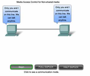
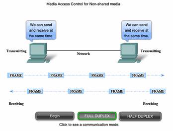
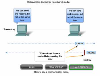
Full Duplex and Half Duplex
In point-to-point connections, the Data Link layer has to consider whether the communication is half-duplex or full-duplex.
Click the tabs in the figure to see the differences in the two methods.
Half-duplex communication means that the devices can both transmit and receive on the media but cannot do so simultaneously. Ethernet has established arbitration rules for resolving conflicts arising from instances when more than one station attempts to transmit at the same time.
In full-duplex communication, both devices can transmit and receive on the media at the same time. The Data Link layer assumes that the media is available for transmission for both nodes at any time. Therefore, there is no media arbitration necessary in the Data Link layer.
The details of a specific media access control technique can only be examined by studying a specific protocol. Within this course, we will study traditional Ethernet, which uses CSMA/CD. Other techniques will be covered in later courses.
7.2.4 Logical VS Physical
The topology of a network is the arrangement or relationship of the network devices and the interconnections between them. Network topologies can be viewed at the physical level and the logical level.
The physical topology is an arrangement of the nodes and the physical connections between them. The representation of how the media is used to interconnect the devices is the physical topology. These will be covered in later chapters of this course.
A logical topology is the way a network transfers frames from one node to the next. This arrangement consists of virtual connections between the nodes of a network independent of their physical layout. These logical signal paths are defined by Data Link layer protocols. The Data Link layer "sees" the logical topology of a network when controlling data access to the media. It is the logical topology that influences the type of network framing and media access control used.
The physical or cabled topology of a network will most likely not be the same as the logical topology.
Logical topology of a network is closely related to the mechanism used to manage network access. Access methods provide the procedures to manage network access so that all stations have access. When several entities share the same media, some mechanism must be in place to control access. Access methods are applied to networks to regulate this media access. Access methods will be discussed in more detail later.
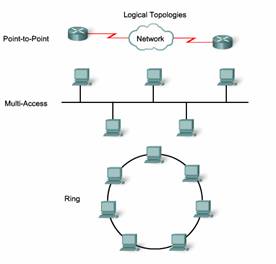
Logical and physical topologies typically used in networks are:
- Point-to-Point
- Multi-Access
- Ring
The logical implementations of these topologies and their associated media access control methods are considered in the following sections.
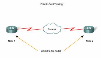
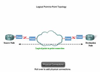
7.2.5 Point-to-Point Technology
A point-to-point topology connects two nodes directly together, as shown in the figure. In data networks with point-to-point topologies, the media access control protocol can be very simple. All frames on the media can only travel to or from the two nodes. The frames are placed on the media by the node at one end and taken off the media by the node at the other end of the point-to-point circuit.
In point-to-point networks, if data can only flow in one direction at a time, it is operating as a half-duplex link. If data can successfully flow across the link from each node simultaneously, it is a full-duplex link.
Data Link layer protocols could provide more sophisticated media access control processes for logical point-to-point topologies, but this would only add unnecessary protocol overhead.
Logical Point-to-Point Networks
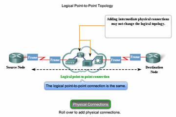
The end nodes communicating in a point-to-point network can be physically connected via a number of intermediate devices. However the use of physical devices in the network does not affect the logical topology. As shown in the figure, the source and destination node may be indirectly connected to each other over some geographical distance. In some cases, the logical connection between nodes forms what is called a virtual circuit. A virtual circuit is a logical connection created within a network between two network devices. The two nodes on either end of the virtual circuit exchange the frames with each other. This occurs even if the frames are directed through intermediary devices. Virtual circuits are important logical communication constructs used by some Layer 2 technologies.
The media access method used by the Data Link protocol is determined by the logical point-to-point topology, not the physical topology. This means that the logical point-to-point connection between two nodes may not necessarily be between two physical nodes at each end of a single physical link.
|
